Display Usage
1. Display Introduction
The RK3588 VOP (video output process) is divided into 4 Ports:
| Port | Resolution |
|---|---|
| VP0 | 4K |
| VP1 | 4K |
| VP2 | 4K |
| VP3 | 1080P |
The connection between RK3588 VP and various display interfaces:
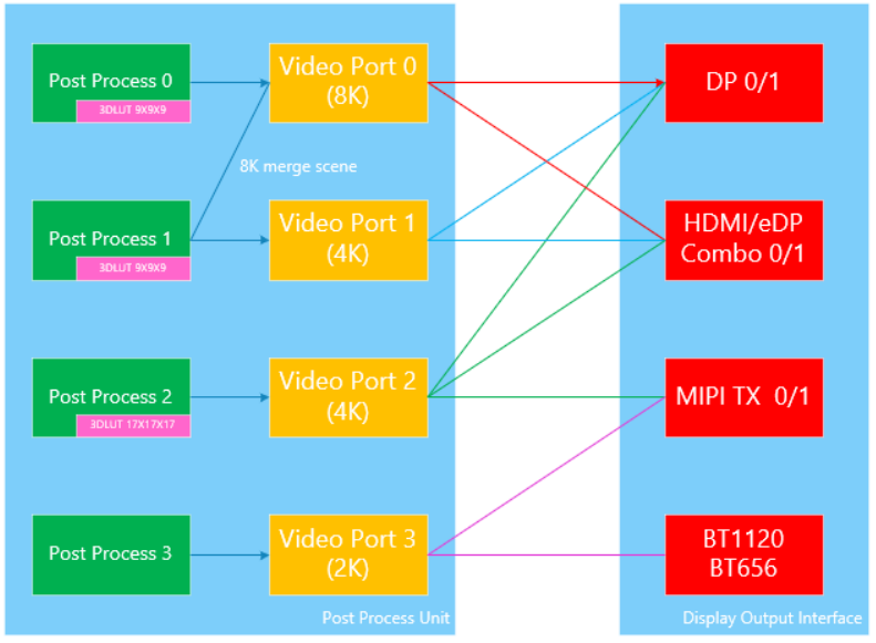
It is important to note that the RK3588's HDMI and DP support 8K output, but in 8K output mode, one display interface needs to occupy both VP0 and VP1 simultaneously. Therefore, if 8K display output is required on the product, be careful not to connect other display interfaces to VP1.
1.2 Display Interfaces Supported by RK3588
- 2 DP
- 2 HDMI/eDP shared interfaces
- 2 MIPI DSI
- BT656/BT1120
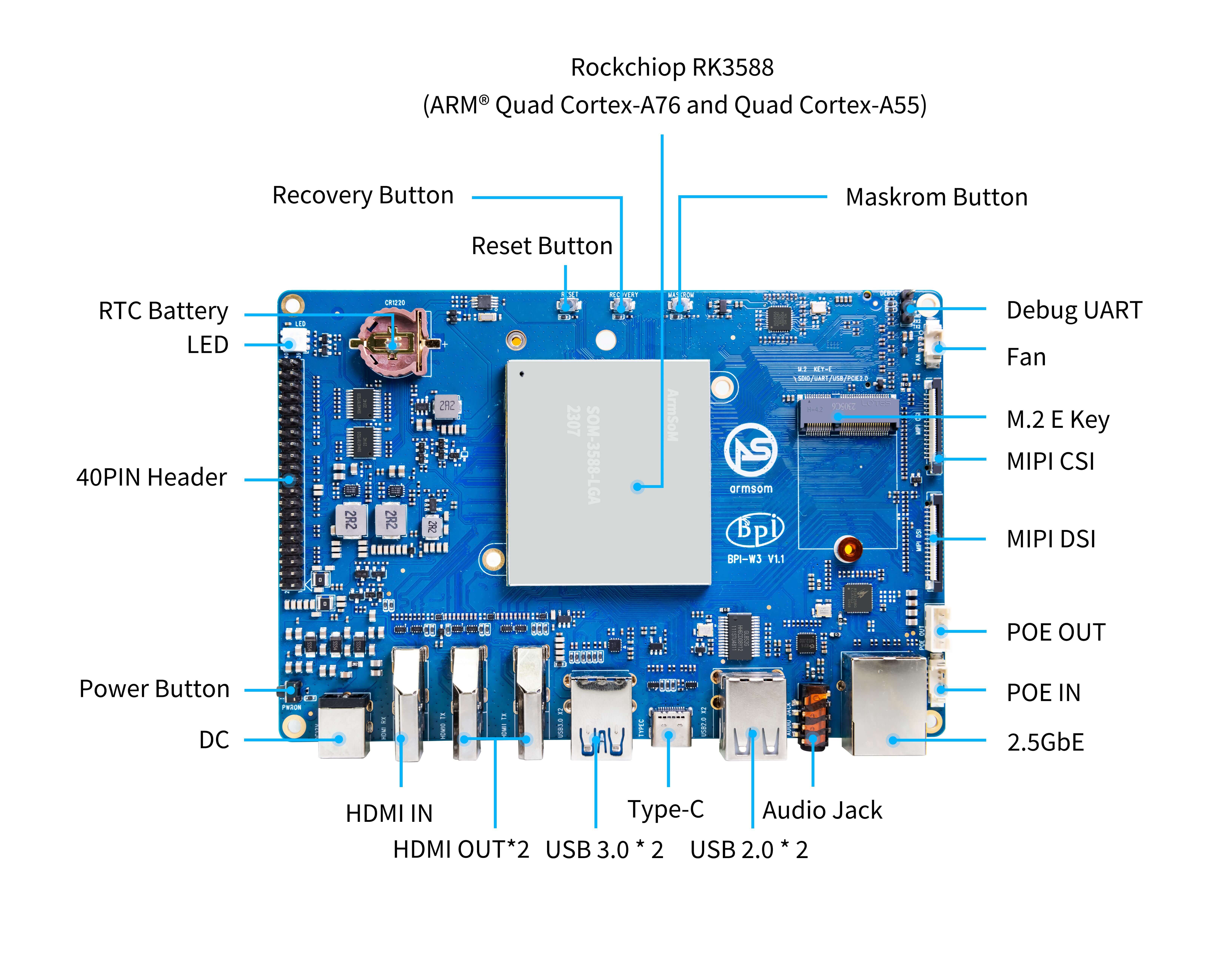
2. ArmSoM-W3 Display Interfaces
ArmSoM-W3 has rich display interfaces. It supports up to four display outputs: two HDMI outputs, one MIPI-DSI output, and one DP interface. Multi-screen display/different display is supported.
Below is a basic introduction to the configuration and usage of each display output interface.
3. HDMI
- ArmSoM-W3 hardware has two HDMI display output interfaces: 2x HDMI OUT2.1
- One HDMI OUT supports 8K@60fps or 4K@120fps, and the other HDMI OUT supports 4K@60fps
3.1 HDMI-related DTS Configuration
- kernel\arch\arm64\boot\dts\rockchip\rk3588-armsom-w3.dts
//Enable HDMI0 function
&hdmi0 {
        status = "okay";
};

//Enable HDMI0 hardware phy
&hdptxphy_hdmi0 {
        status = "okay";
};

//Configure HDMI0 to VP0
&hdmi0_in_vp0 {
        status = "okay";
};

//Enable HDMI0 audio output
&hdmi0_sound {
        status = "okay";
};

//Configure HDMI0 to display boot logo
&route_hdmi0 {
        status = "okay";
};

//Enable hdmi1 function
&hdmi1 {
        status = "okay";
};

//Enable hdmi1 hardware phy
&hdptxphy_hdmi1 {
    status = "okay";
};

//Configure HDMI1 to VP1
&hdmi1_in_vp1 {
        status = "okay";
};

//Enable HDMI1 audio output
&hdmi1_sound {
        status = "okay";
};

//Configure HDMI1 to display boot logo
&route_hdmi1 {
        status = "okay";
};
4. DP
ArmSoM-W3 hardware has one Type-C interface output DP, with a resolution up to 8192x4320@30Hz, and the PHY link rate can reach 8.1Gbps/lane.
4.1 DTS Configuration
4.1.1 DP Controller Configuration:
&dp0 {
status = "okay";
};
&dp0_in_vp2 {
status = "okay";
};
4.1.2 PHY Configuration:
&usbdp_phy0 {
    status = "okay";
    orientation-switch;
    svid = <0xff01>;
    sbu1-dc-gpios = <&gpio4 RK_PA6 GPIO_ACTIVE_HIGH>;
    sbu2-dc-gpios = <&gpio4 RK_PA7 GPIO_ACTIVE_HIGH>;

    port {
        #address-cells = <1>;
        #size-cells = <0>;
        usbdp_phy0_orientation_switch: endpoint@0 {
            reg = <0>;
            remote-endpoint = <&usbc0_orien_sw>;
        };

        usbdp_phy0_dp_altmode_mux: endpoint@1 {
            reg = <1>;
            remote-endpoint = <&dp_altmode_mux>;
        };
    };
};
4.1.3 Configure PD Chip for Type-C Interface
The Type-C interface needs to configure the lane and HPD status through CC detection and PD negotiation of Type-C, so you also need to configure the PD chip (currently supported PD chips are fusb302, husb311):
&i2c4 {
    status = "okay";
    pinctrl-names = "default";
    pinctrl-0 = <&i2c4m1_xfer>;

    usbc0: fusb302@22 {
        compatible = "fcs,fusb302";
        reg = <0x22>;
        interrupt-parent = <&gpio3>;
        interrupts = <RK_PB4 IRQ_TYPE_LEVEL_LOW>;
        int-n-gpios = <&gpio3 RK_PB4 GPIO_ACTIVE_LOW>;
        pinctrl-names = "default";
        pinctrl-0 = <&usbc0_int>;
        //vbus-supply = <&vcc12v_dcin>;
        vbus-supply = <&vbus5v0_typec>;
        status = "okay";

        ports {
            #address-cells = <1>;
            #size-cells = <0>;

            port@0 {
                reg = <0>;
                usbc0_role_sw: endpoint@0 {
                    remote-endpoint = <&dwc3_0_role_switch>;
                };
            };
        };

        usb_con: connector {
            compatible = "usb-c-connector";
            label = "USB-C";
            data-role = "dual";
            power-role = "dual";
            try-power-role = "sink";
            op-sink-microwatt = <1000000>;
            sink-pdos =
                <PDO_FIXED(5000, 3000, PDO_FIXED_USB_COMM)
                 PDO_FIXED(9000, 3000, PDO_FIXED_USB_COMM)
                 PDO_FIXED(12000, 3000, PDO_FIXED_USB_COMM)>;
            source-pdos =
                <PDO_FIXED(5000, 3000, PDO_FIXED_USB_COMM)>;

            altmodes {
                #address-cells = <1>;
                #size-cells = <0>;

                altmode@0 {
                    reg = <0>;
                    svid = <0xff01>;
                    vdo = <0xffffffff>;
                };
            };

            ports {
                #address-cells = <1>;
                #size-cells = <0>;

                port@0 {
                    reg = <0>;
                    usbc0_orien_sw: endpoint {
                        remote-endpoint = <&usbdp_phy0_orientation_switch>;
                    };
                };

                port@1 {
                    reg = <1>;
                    dp_altmode_mux: endpoint {
                        remote-endpoint = <&usbdp_phy0_dp_altmode_mux>;
                    };
                };
            };
        };
    };
};
4.1.4 Configure DP Boot Logo
 &route_dp0 {
    status = "okay";
    connect = <&vp2_out_dp0>;
};
Note that the connect property here configures DP to bind to VOP Port2 in the U-Boot stage, so the dtsi configuration must allow DP to bind to VOP Port2:
&dp0_in_vp2 {
    status = "okay";
};
Type-C DP boot logo is not supported yet!
4.2 Debugging
4.2.1 Check Connector Status:
Under the /sys/class/drm directory, you can see the cards registered by the driver, where card0-DP-1 is the DP display device.
armsom@armsom:~$ ls /sys/class/drm/
card0  card0-DP-1  card0-HDMI-A-1  card0-Writeback-1  card1  renderD128  renderD129  version
Taking card0-DP-1 as an example, its directory contains the following:
armsom@armsom:~$ ls /sys/class/drm/card0-DP-1/
device  dpms  edid  enabled  modes  power  status  subsystem  uevent
enabled -to check the enable status:
armsom@armsom:~$ cat /sys/class/drm/card0-DP-1/enabled
disabled
status- to check the connection status:
armsom@armsom:~$ cat /sys/class/drm/card0-DP-1/status
disconnected
4.2.2 Force Enable/Disable DP
#Force disable DP
rk3588_s:/ # echo off > /sys/class/drm/card0-DP-1/status
#Force enable DP
rk3588_s:/ # echo on > /sys/class/drm/card0-DP-1/status
#Restore hot-plug detection
rk3588_s:/ # echo detect > /sys/class/drm/card0-DP-1/status
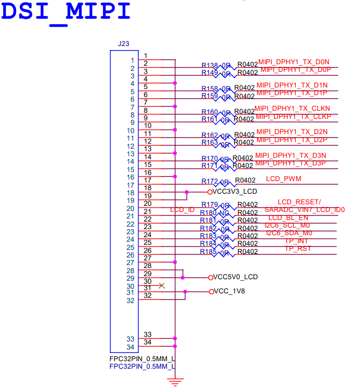
5. MIPI DSI
ArmSoM-W3 hardware has one MIPI-DSI display output interface, supporting DPHY2.0 and 4 Lane data output, with a resolution up to 4K@60Hz.
5.1 Schematic
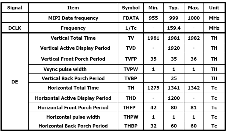
5.2 Screen Display Timing Diagram
5.3 MIPI DSI-related DTS Configuration
5.3.1 Backlight Configuration
dsi1_backlight: dsi1-backlight {
        status = "okay";
        compatible = "pwm-backlight";
        pwms = <&pwm2 0 25000 0>;
        brightness-levels = <
              0  20  20  21  21  22  22  23
             23  24  24  25  25  26  26  27
             27  28  28  29  29  30  30  31
             31  32  32  33  33  34  34  35
             35  36  36  37  37  38  38  39
             40  41  42  43  44  45  46  47
             48  49  50  51  52  53  54  55
             56  57  58  59  60  61  62  63
             64  65  66  67  68  69  70  71
             72  73  74  75  76  77  78  79
             80  81  82  83  84  85  86  87
             88  89  90  91  92  93  94  95
             96  97  98  99 100 101 102 103
            104 105 106 107 108 109 110 111
            112 113 114 115 116 117 118 119
            120 121 122 123 124 125 126 127
            128 129 130 131 132 133 134 135
            136 137 138 139 140 141 142 143
            144 145 146 147 148 149 150 151
            152 153 154 155 156 157 158 159
            160 161 162 163 164 165 166 167
            168 169 170 171 172 173 174 175
            176 177 178 179 180 181 182 183
            184 185 186 187 188 189 190 191
            192 193 194 195 196 197 198 199
            200 201 202 203 204 205 206 207
            208 209 210 211 212 213 214 215
            216 217 218 219 220 221 222 223
            224 225 226 227 228 229 230 231
            232 233 234 235 236 237 238 239
            240 241 242 243 244 245 246 247
            248 249 250 251 252 253 254 255
        >;
        default-brightness-level = <200>;
        enable-gpios = <&gpio2 RK_PC2 GPIO_ACTIVE_HIGH>;
        pinctrl-names = "default";
        pinctrl-0 = <&dsi1_backlight_en>;
    };
5.3.2 Screen Power-on Sequence and Parameter Configuration
&dsi1 {
    status = "okay";
    dsi1_panel: panel@0 {
        status = "okay";
        compatible = "simple-panel-dsi";
        reg = <0>;
        power-supply = <&vcc_lcd_mipi1>;  //use gpio simulated regulator
        reset-gpios = <&gpio2 RK_PC1 GPIO_ACTIVE_LOW>;
        backlight = <&dsi1_backlight>;
        pinctrl-names = "default";
        pinctrl-0 = <&dsi1_lcd_rst_gpio>;
        reset-delay-ms = <10>;
        enable-delay-ms = <10>;
        prepare-delay-ms = <10>;
        unprepare-delay-ms = <10>;
        disable-delay-ms = <10>;
        dsi,flags = <(MIPI_DSI_MODE_VIDEO | MIPI_DSI_MODE_VIDEO_BURST |
            MIPI_DSI_MODE_LPM | MIPI_DSI_MODE_EOT_PACKET)>;
        dsi,format = <MIPI_DSI_FMT_RGB888>;
        dsi,lanes  = <4>;
        panel-init-sequence = [
            15 00 02 B0 01
            15 00 02 C0 26
            15 00 02 C1 10
            15 00 02 C2 0E
            15 00 02 C3 00
            15 00 02 C4 00
            15 00 02 C5 23
            15 00 02 C6 11
            15 00 02 C7 22
            15 00 02 C8 20
            15 00 02 C9 1E
            15 00 02 CA 1C
            15 00 02 CB 0C
            15 00 02 CC 0A
            15 00 02 CD 08
            15 00 02 CE 06
            15 00 02 CF 18
            15 00 02 D0 02
            15 00 02 D1 00
            15 00 02 D2 00
            15 00 02 D3 00
            15 00 02 D4 26
            15 00 02 D5 0F
            15 00 02 D6 0D
            15 00 02 D7 00
            15 00 02 D8 00
            15 00 02 D9 23
            15 00 02 DA 11
            15 00 02 DB 21
            15 00 02 DC 1F
            15 00 02 DD 1D
            15 00 02 DE 1B
            15 00 02 DF 0B
            15 00 02 E0 09
            15 00 02 E1 07
            15 00 02 E2 05
            15 00 02 E3 17
            15 00 02 E4 01
            15 00 02 E5 00
            15 00 02 E6 00
            15 00 02 E7 00
            15 00 02 B0 03
            15 00 02 BE 04
            15 00 02 B9 40
            15 00 02 CC 88
            15 00 02 C8 0C
            15 00 02 C9 07
            15 00 02 CD 01
            15 00 02 CA 40
            15 00 02 CE 1A
            15 00 02 CF 60
            15 00 02 D2 08
            15 00 02 D3 08
            15 00 02 DB 01
            15 00 02 D9 06
            15 00 02 D4 00
            15 00 02 D5 01
            15 00 02 D6 04
            15 00 02 D7 03
            15 00 02 C2 00
            15 00 02 C3 0E
            15 00 02 C4 00
            15 00 02 C5 0E
            15 00 02 DD 00
            15 00 02 DE 0E
            15 00 02 E6 00
            15 00 02 E7 0E
            15 00 02 C2 00
            15 00 02 C3 0E
            15 00 02 C4 00
            15 00 02 C5 0E
            15 00 02 DD 00
            15 00 02 DE 0E
            15 00 02 E6 00
            15 00 02 E7 0E
            15 00 02 B0 06
            15 00 02 C0 A5
            15 00 02 D5 1C
            15 00 02 C0 00
            15 00 02 B0 00
            15 00 02 BD 30

            15 00 02 F9 5C
            15 00 02 C2 14
            15 00 02 C4 14
            15 00 02 BF 15
            15 00 02 C0 0C


            15 00 02 B0 00
            15 00 02 B1 79
            15 00 02 BA 8F

            05 78 01 11
            05 78 01 29
        ];

        panel-exit-sequence = [
            05 32 01 28
            05 78 01 10
        ];

        disp_timings1: display-timings {
            native-mode = <&dsi1_timing0>;
            dsi1_timing0: timing0 {
                clock-frequency = <160000000>;
                hactive = <1200>;
                vactive = <1920>;
                hfront-porch = <80>;
                hsync-len = <1>;
                hback-porch = <60>;
                vfront-porch = <35>;
                vsync-len = <1>;
                vback-porch = <25>;
                hsync-active = <0>;
                vsync-active = <0>;
                de-active = <0>;
                pixelclk-active = <1>;
            };
        };
        ports {
            #address-cells = <1>;
            #size-cells = <0>;

            port@0 {
                reg = <0>;
                panel_in_dsi1: endpoint {
                    remote-endpoint = <&dsi1_out_panel>;
                };
            };
        };
    };
    ports {
        #address-cells = <1>;
        #size-cells = <0>;

        port@1 {
            reg = <1>;
            dsi1_out_panel: endpoint {
                remote-endpoint = <&panel_in_dsi1>;
            };
        };
    };
};
5.3.3 Open the corresponding dsi node, boot logo
//Open the backlight pwm node
    &pwm2 {
        status = "okay";
        pinctrl-names = "active";
        pinctrl-0 = <&pwm2m2_pins>;
    };

    //A mipi screen is connected to dsi1, this configuration enables dsi1
     &dsi1 {
        status = "okay";
    };

    &mipi_dcphy1 {
        status = "okay";
    };

    //By default, dsi is configured on vp2 and vp3, here it is configured to use vp3 for dsi, which can be determined by the screen resolution to use vp2 or vp3, vp2 supports 4K, vp3 only supports 2048x1536
    &dsi1_in_vp2 {
        status = "disabled";
    };

    &dsi1_in_vp3 {
        status = "okay";
    };

    //Configure dsi1 to display boot logo
    &route_dsi1 {
        status = "okay";
        connect = <&vp3_out_dsi1>;
    };
5.4. Debugging
The VOP status can be queried through the following command:
cat /sys/kernel/debug/dri/0/summary
The obtained VOP status is shown in the following image:
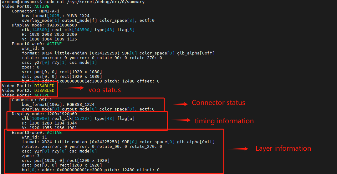
- Video Portx: Indicates the current status of the Video Port
- Connector: Output interface currently connected to the Video Port
- Display mode: Current output timing of the Video Port
- Clusterx-winx(Esmartx-winx): Layer information
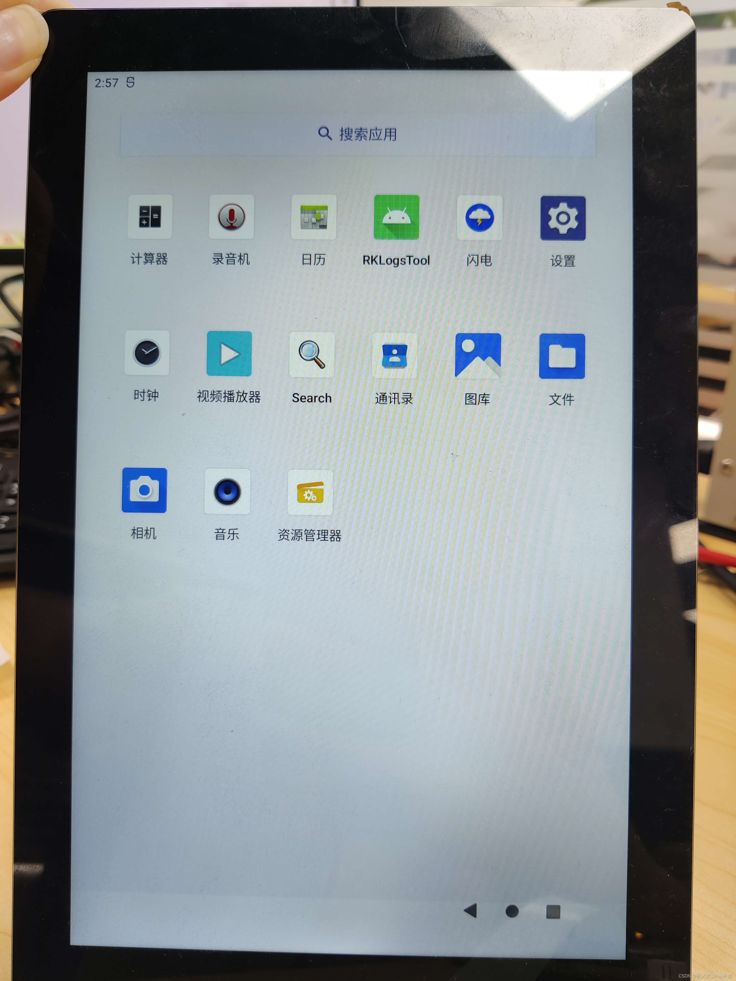
5.5 MIPI-DSI Preview